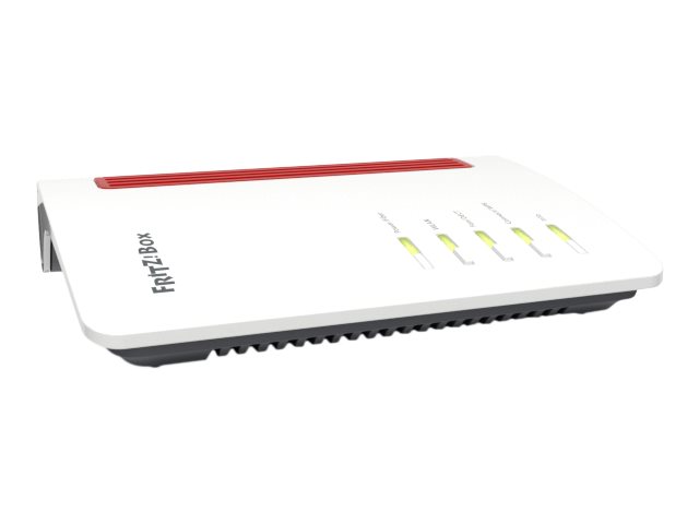
AVM FRITZ!BOX 5590 Fiber
Artikel-Nr.:
211064
EAN:
4023125029813
Herstellernummer:
20002981
Intrastat ID:
85176200
Garantie:
24 Monate
Gewicht:
1,150 KG
Produktinformationen "AVM FRITZ!BOX 5590 Fiber"
• Herstellergarantie: fünf Jahre
 Kupplung/Patchkabel,")
Rackmount.IT, Rack Mount Kit for AVM FRITZ!Box 4690/5590/6660 Cable/6670 Cable/7590 AX/7690, UTP(ungeschirmte) Kupplung/Patchkabel,
* Auftragsbezogen, nicht Stornierbar *,
Entdecken Sie den RM-FB-T7, Ihre ausgezeichnete Lösung für die nahtlose Integration Ihres appliance in ein 19"-Rack. Dieses Rack ist speziell für die aufgeführten Modelle maßgeschneidert, um bei jeder Anwendung eine perfekte und sichere Passform zu gewährleisten. Dank praktischer Frontanschlüsse war der Zugriff auf Ihre Konfiguration noch nie so einfach.
Sorgen Sie sich um einen versehentlichen Stromausfall? Keine Sorge! Das Netzteil ist fest am Rack befestigt, was für Sicherheit und ununterbrochene Funktionalität sorgt.
Der Zusammenbau Ihrer Konfiguration ist ein Kinderspiel und dauert weniger als 3 Minuten von Anfang bis Ende. Schieben Sie einfach Ihr Gerät in das Kit, sichern Sie es mit den Halterungen, schließen Sie die mitgelieferten Kabel an die Keystone-Buchsen an und befestigen Sie das Netzteil am Rack - so einfach ist das!
Erleben Sie eine nahtlose Integration und mühelosen Zusammenbau mit dem RM-FB-T7 - Ihrer bevorzugten Lösung für professionelles Rack-Mounting!
Artikel-Nr.:
244220
Herstellernummer:
RM-FB-T7
Bestand:
27x
Sofort verfügbar, Lieferzeit: 1-2 Tage

AVM FRITZ!BOX 55xx Fiber zbh. AON Ersatz GBIC "ALL4786-AON"
AVM FRITZ!BOX 5530 Fiber zbh. AON Ersatz GBIC "ALL4786-AON"
ACHTUNG:
Funktioniert in einem ONT. Dieses GBIC ist nur die Fibre-Wellen-GBIC für den Standard AON. Es wir noch immer ein passendes ONT benötigt mit der dazugehörigen Modem-ID.
Highlights:
ITU-T G.652; IEEE 802.3ah-2004 1000BASE-BX10
LC-APC 8°
Wellenlänge: TX 1310 nm, RX 1480 bis 1580 nm
Full duplex Übertragung
Sendeleistung: -9 bis -3 dBm
Empfangsleistungsbereich: -3 bis -23 dBm
Reichweite: 10 km
Unterstützung von SFF-8472
Laser Klasse 1
Kompatibel zu AVM Fritz Art. 2000 2940
Technical Details:
1.25Gbps BiDi LC/APC 20Km SFP Transceiver ALL4786-AON
Product Features
Up to 1.25Gbps data links
20Km with 9/125µm SMF
Tx1310nm/ Rx1490nm
BiDi Simplex LC/APC Connector
Hot-pluggable SFP footprint
Single 3. 3V power supply
Operating temperature: 0~70?
DDMI
SFF-8472-Compliance
RoHS
Applications
√ 1.25Gbps 1000Base-LX
PART NUMBER
WAVE LENGTH TX/RX
DISTANCE
LASER
TEMPERATURE
ALL4786-AON
1310nm/1490nm
20km
FP/PIN
0~70?
Product Description
The ALLNET ALL4786-AON SFP is small form factor pluggable (SFP) transceivers compatible with multi-sourcing agreement (MSA). It is suitable for single-mode fiber (SMF) communications in 1.25Gbps Ethernet and 1G/2G Fiber Channel.
Regulatory Compliance
ALLNET ALL4786-AON transceivers are Class 1 Laser Products comply with FDA regulations. Meet Class 1 eye safety requirements of EN 60825 and the electrical safety requirements of EN 60950.
Absolute Maximum Ratings
Parameter
Symbol
Min.
Max.
Unit
Supply Voltage
VCC
-0.5
3.6
V
Storage Temperature
TS
-40
85
°C
Operating Case Temperature
TC
0
70
°C
Recommended Operating Conditions
Parameter
Symbol
Min.
Typical
Max.
Unit
Operating Case Temperature
TC
0
70
°C
Power Supply Voltage
VCC
3.15
3.3
3.45
V
Power Supply Current
ICC
300
mA
Data Rate
1.25
GBps
Max Link Length on 9/125µm SMF
Lmax
20
km
Electrical Characteristics
Parameter
Symbol
Min.
Typical
Max.
Unit
Transmitter
Input Differential Impedance
Zin
90
100
110
Ω
Data Input Swing Differential
Vin
500
2400
mV
Tx-Dis Disable
Vd
2.0
Vcc
V
Tx-Dis Enable
Ven
0
0.8
V
TX-Fault (Fault)
2.0
Vcc+0.3
V
TX-Fault (Normal)
0
0.8
V
Receiver
Data Output Swing Differential
Vout
370
2000
mV
Rx-Los Fault
Vlf
2.0
Vcc+0.3
V
Rx-Los Normal
Vln
0
0+0.8
V
Optical Characteristics
Parameter
Symbol
Min.
Typical
Max.
Unit
Transmitter
Centre Wavelength
λc
1290
1310
1330
nm
Spectral Width (RMS)
σ
4
nm
Average Output Power
Pout
-9
-3
dBm
Extinction Ratio
ER
9
dB
Optical Rise/Fall Time
tr/tf
2
ns
Receiver
Centre Wavelength
λc
1470
1490
1610
nm
Receiver Sensitivity
PIN
-23
dBm
Receiver Overload
PMAX
-3
dBm
LOS De-Assert
LOSD
-30
dBm
LOS Assert
LOSA
-35
dBm
LOS Hysteresis
0.5
4.5
dB
Pin Descriptions
Pin
Symbol
Description
Ref.
1
VEET
Transmitter Ground (Common with Receiver Ground)
6.1
2
TFAULT
Transmitter Fault. Not supported.
3
TDIS
Transmitter Disable. Laser output disabled on high or open.
6.2
4
MOD_DEF(2)
Module Definition 2. Data line for Serial ID.
6.3
5
MOD_DEF(1)
Module Definition 1. Clock line for Serial ID.
6.3
6
MOD_DEF(0)
Module Definition 0. Grounded within the module.
6.3
7
Rate Select
No connection required
8
LOS
Loss of Signal indication. Logic 0 indicates normal
operation.
6.4
9
VEER
Receiver Ground (Common with Transmitter Ground)
6.1
10
VEER
Receiver Ground (Common with Transmitter Ground)
6.1
11
VEER
Receiver Ground (Common with Transmitter Ground)
6.1
12
RD-
Receiver Inverted DATA out. AC Coupled.
13
RD+
Receiver Non-inverted DATA out. AC Coupled.
14
VEER
Receiver Ground (Common with Transmitter Ground)
6.1
15
VCCR
Receiver Power Supply
16
VCCT
Transmitter Power Supply
17
VEET
Transmitter Ground (Common with Receiver Ground)
6.1
18
TD+
Transmitter Non-Inverted DATA in. AC Coupled.
19
TD-
Transmitter Inverted DATA in. AC Coupled.
20
VEET
Transmitter Ground (Common with Receiver Ground)
6.1
Notes:
Circuit ground is internally isolated from chassis ground.
Laser output disabled on TDIS >2.0V or open, enabled on TDIS <0.8V.
Should be pulled up with 4.7k - 10kohms on host board to a voltage between 2.0V and 3.6V. MOD_DEF(0) pulls line low to indicate module is plugged in.
LOS is open collector output. Should be pulled up with 4.7k -10kohms on host board to a voltage between 2.0V and 3.6V. Logic 0 indicates normal operation; logic 1 indicates loss of signal.
EEPROM & DDM THRESHOLD
EEPROM
2 wire address 1010000X (A0hex)
0~95
Serial ID Defined by SFP MSA (96 bytes)
96~127
Vendor Speific (32 bytes)
128~255
Reserved (128 bytes)
*Customized Area
Address
Description
Hex Data
ASCII
A0 20~35
Vendor Name
41 4c 4c 4e 45 54 20 47 6d 62 48
ALLNET GmbH
DDM THRESHOLD
ALL4786-AON
Low Alarm
Low Warn
High Warn
High Alarm
Temp
-5?
0?
70?
75?
Voltage
3V
3.1V
3.6V
3.7V
Tx Bias
3mA
4mA
70mA
75mA
Tx Power
-13.5dBm
-9.5dBm
-1dBm
1dBm
Rx Power
-23dBm
-19dBm
-3dBm
1dBm
Recommend Circuit
Mechanical Specifications
Recommend Circuit
Mechanical Specifications
Artikel-Nr.:
217024
Herstellernummer:
ALL4786-AON
Bestand:
27x
Sofort verfügbar, Lieferzeit: 1-2 Tage